Garage plans by Behm Design
are accurate, complete and of highest drafting standards for clarity of information. 1/4″ = 1′-0″ scale is used for all plan, elevation and section views in the drawings. Larger scales are used for details as appropriate. The industry standard for architectural drawings are 2-dimensional drawing views and must be part of a building permit drawing submittal. 3-dimensional views like isometric, axonometric and perspective views alone are not usually accepted for building permit, construction drawings.
Our plans include the following:
- Sheet 1 is the cover with the design illustration, materials list and design data (code references, etc.)
- Floor Plan(s) showing walls, openings, dimensions, and symbols for electrical lighting, switching and outlet locations
- the 4 exterior elevation views (true elevations)
- Exterior wall framing only elevations (sometimes included with the regular elevations with framing shown as dashed lines)
- Roof edge details for soffits, eaves and gable ends as applicable
- Perimeter Foundation and slab plan showing openings and dimensions
- Concrete foundation details and alternates
- Cross Sections and longitudinal if applicable
- Structure notes and specifications
- Typical and other wall sections
- Roof framing or truss layout plan (shows truss requirements – but engineering will be by the local truss fabricator, which is required by State law)
- Second-floor framing plan if required
- Stairway profile and details if applicable
- Garage plan modifications are not available. However, many of our garage plans include variable write-ins for dimension, wall height, roof slope, alternates for garage door size. Since the plans are prescriptive with the IRC code these minor alternate selections are usually allowed by the building dept. However there are some that do not allow them. We recommend checking with the building dept. that before submitting for the plan review to make sure they allow.
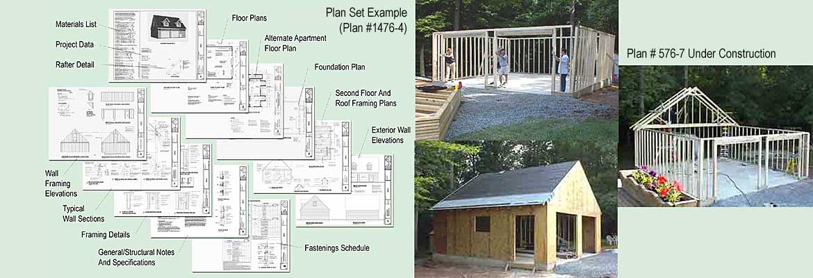
This collage/image was made using one of our garage plans which has 11 sheets. To illustrate the overall content of typical garage plans produced by Behm Design individual plan sheets were reduced and then layered in Photoshop. The sheet size we use for all of our garage plans is 18″ x 24″. There is some content common to many of the plan but most plans are unique with 1/4″ scale full views. Paper plans are sold in a package of four copies. They are collated and stapled and shipped by UPS Ground or USPS Priority Mail for PO box addresses. Alternatively, you can purchase the PDF for the plan and it is the exact same file that the paper plans are printed from. In Checkout, you can buy extra copies as add-ons.
Regarding Drawing Scale:
Scale is used in the drawing views to illustrate the design and relative proportions. It is important to note that the drawings should never be scaled directly. That is because some framing dimensions, spacings and allowances can change when wall bracing schemes are calculated for a code change, for example. The drawings are not revised unless the actual framing or assembly is changed. Laying an architectural scale on 1/4″ scale drawings may seem to be a discrepancy but it is not. Where the change occurs is in the indicated dimension lines and values throughout the drawings. This is standard practice in our industry. If you do scale the actual prints you might conclude there is an error. There is not. But using scale-derived measurements will create building errors.
Regarding Drawing Dimensions:
All dimensions are presented in appropriate views. Dimensions that are not shown are those that are established when various components, such as windows and doors, etc. are selected from your supplier. And that us due to manufacturers’ variations. You may wonder why we dimension openings in framed walls – it is because you will later learn what the window manufacturer requires for their product. You then frame to that from the located center of opening. Framing dimensions for walls are to one face of framing to another. For framed bearing lines(which may be posts, beams or bearing walls) are referenced to centerlines of the bearing structure. Concrete dimensions are to face of concrete of foundation walls and their openings. Concrete post footings are located to centerlines and sizes of footings are called out in a note.
So why do we sell a package of 4 copies of the plan?
When you make your application to the building department for a permit they were usually 2 copies for record and inspector. The other 2 are for the contractor and yourself or the supplier. When a permit is granted it is required to keep one of the officially approved and sealed plans, unaltered, for the building inspector.